
DUAL 15-3 (X330)
120 sheets notebook with hard cover made of recycled cardboard. 16x22cm

(edit with the Customer Reassurance module)

(edit with the Customer Reassurance module)

(edit with the Customer Reassurance module)
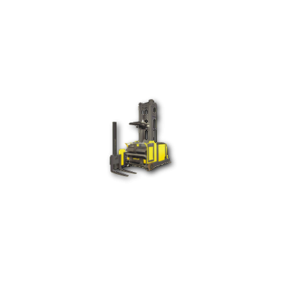
STILL STED Forklift DUAL15-3 Workshop Manual – PDF DOWNLOAD
FILE DETAILS:
STILL STED Forklift DUAL15-3 Workshop Manual – PDF DOWNLOAD
Language : English
Pages : 569
Downloadable : Yes
File Type : PDF
DESCRIPTION:
STILL STED Forklift DUAL15-3 Workshop Manual – PDF DOWNLOAD
IMAGES PREVIEW OF THE MANUAL:


TABLE OF CONTENTS:
STILL STED Forklift DUAL15-3 Workshop Manual – PDF DOWNLOAD
• List of chapters P 19
• Guide to components P 22
• Chapter 1: Vehicle data
– Guide to information plates and vehicle number P 1-01
– Hydraulic settings P 1-02
– Hydraulic settings P 1-02 1 (DUAL13-3)
– Vehicle speed P 1-03
• Outside aisle P 1-03
• Inside aisle P 1-03
• Chapter 2: Drive motor
– General P 2-01
– Technical data for the drive motor P 2-01
– Drive mor terminals P 2-01
– Temperature sensor integrated in the
carbon brush yoke P 2-02
– Carbon brush monitoring P 2-03
– Replacing the carbon brushes P 2-04
– Checking the brush springs P 2-04
– Removing the drive motor P 2-05
– Installing the drive motor P 2-06
– Drive motor maintenance P 2-07
For Alternating Current only:
– General P 2-11 (DUAL15-3AC)
– Terminals P 2-12 (DUAL15-3AC)
– Speed monitoring P 2-13 (DUAL15-3AC)
– Removal P 2-14 (DUAL15-3AC)
– Technical data P 2-15 (DUAL15-3AC)
– Temperature monitoring P 2-16 (DUAL15-3AC)
– Speed sensor P 2-17 (DUAL15-3AC)
• Removal P 2-17 (DUAL15-3AC)
• Installation P 2-19 (DUAL15-3AC)
• Chapter 3: Drive wheel
– Replacing the drive wheel P 3-01
– Removing the drive wheel P 3-01
– Replacing the idling wheels P 3-02
– Removing the idling wheels P 3-02
– Installing the idling wheels P 3-02
• Chapter 4: Gear
– Oil change P 4-01
– Removing the gear P 4-02
Copyright protected No part of this manual
may be reproduced in any form Copyright
reserved
Issue: 07/03 Workshop Sheet no
Replaces issue: 06/02 Manual DUAL15-3 4
List of contents
• Chapter 5: Brake
– Electromagnetic brake P 5-01
• Function P 5-01
• Removal P 5-02
• Replacing the brake linings P 5-03
• Adjusting the brake clearance P 5-04
• Mechanical brake release P 5-05
• Testing the brake coils P 5-05
• Continuous release of the second stage P 5-06
• Continuous release of the second stage P 5-06 1 (DUAL13-3)
• Measuring the braking deceleration P 5-07
• Checking the braking deceleration P 5-08
• Checking the braking deceleration P 5-08 1 (DUAL13-3)
• Adjusting the braking deceleration P 5-10
• Adjusting the braking deceleration P 5-10 1 (DUAL13-3)
• Chapter 6: Steering
– Adjusting the steering P 6-01
• General P 6-01
• Adjusting sequence P 6-02
• Turning the potentiometer of the steering controller
to the centre position P 6-03
• Adjusting the rotary force at the handwheel P 6-04
• Adjusting the retaining force in the straight-on position P 6-04
• Adjusting potentiometers R11/R12 P 6-05
• Adjusting the setpoint potentiometers P 6-06
• Adjusting the actual value potentiometer (to approx 11/02) P 6-07
• Adjusting the actual value potentiometer (from approx 11/02) P 6-07 1
• Adjusting the max steering angle P 6-08
• Correction of straight-on P 6-09
– Rail guidance P 6-09
– Free travel P 6-09
• Teaching-in the wheel position display P 6-10
– Steering controller P 6-10 1
• Block diagram of steering P 6-10 1
• Block diagram of steering controller P 6-10 2
• Description P 6-11
• Guide to the potentiometer and LEDs P 6-12
• Service switch P 6-12
• Pin assignment P 6-13
• Main current terminals P 6-14
• Maintenance P 6-14 1
– Steering motor P 6-15
• General P 6-15
• Terminal designations on terminal board P 6-15
• Replacing the carbon brushes P 6-15
• Emergency steering P 6-15
• Maintenance P 6-15
Copyright protected No part of this manual
may be reproduced in any form Copyright
reserved
Issue: 07/03 Workshop Sheet no
Replaces issue: 06/02 Manual DUAL15-3 5
List of contents
• Chapter 7: Mast
– Removing the mast P 7-01
– Installing the mast P 7-05
– Mast table P 7-06
• Chapter 8: Vehicle control system 8U60
– General P 8-01
– Description P 8-01
– Replacing the FZS P 8-01 1
– Pin assignment P 8-02
• Chapter 9: Travel and pump controller A10
– General P 9-01
– Terminals P 9-01
– Pin assignment P 9-02
– Block diagram P 9-04
– Signal processing P 9-05
– Response of the main contactors P 9-06
– Control OK P 9-07
– Temperature monitor fo the drive and pump motors P 9-08
• General P 9-08
• Description P 9-08
• Testing the temperature sensors P 9-08
• Contact assignment MARKII P 9-08 1
– Temperature monitor for the travel and pump controller P 9-09
– Carbon brush monitor for the drive and pump motors P 9-10
– Incremental encoder monitor P 9-12
• General P 9-12
• Description P 9-13
• Testing the incremental encoder of the drive motor P 9-14
• Testing the incremental encoder of the pump motor P 9-15
– Instructions for repair P 9-16
• Power unit P 9-16
• Control card P 9-16
• Field regulator P 9-16
– Table of errors P 9-17
– Removing the FPS P 9-18
– Installing the FPS P 9-19
– Removing the control card P 9-20
– Installing the control card P 9-21
– Removing the field regulator P 9-22
– Installing the field regulator P 9-24
For Alternating Current only:
– General P 9-26 (DUAL15-3AC)
– Block diagram P 9-27 (DUAL15-3AC
– Switching on the main contactors P 9-28 (DUAL15-3AC)
• Step-by-step procedure P 9-28 (DUAL15-3AC)
• Activation of the convertors P 9-28 (DUAL15-3AC)
Copyright protected No part of this manual
may be reproduced in any form Copyright
reserved
Issue: 07/03 Workshop Sheet no
Replaces issue: 06/02 Manual DUAL15-3 6
List of contents
– Phase monitoring P 9-29 (DUAL15-3AC)
– Pin assignment for X1 P 9-30 (DUAL15-3AC)
• Chapter 10: Operating console 8U62
– Operating elements P 10-01
– Block diagram P 10-02
– Operating console board P 10-03
– Pin assignment P 10-04
– Keyboard boards 1, 2 and 3 P 10-05
– Operating console display P 10-06
• General P 10-06
• Basic display P 10-07
• Operating hours P 10-07
• Remaining battery capacity P 10-07
• Wheel position display P 10-07
• Display LED for manual steering P 10-08
• Status and maintenance symbols P 10-08
• “Deadman switch not actuated” display P 10-08
• “Creep speed” display P 10-08
• “2-handed operation not actuated” display P 10-09
• “Barrier open” display P 10-09
• “Maintenance” display P 10-09
• “LR80 error” display P 10-09
• “Acknowledgement required” display P 10-10
• “Reserve1” display P 10-10
• “Reserve2” display P 10-10
– Operating console display P 10-11
• Error display P 10-11
• Information display P 10-11 1
• Switching-on test P 10-12
• Switching over the operating console display P 10-12
• LR80 operating status display P 10-12
– Replacing the setpoint potentiometer P 10-13
• Removing the setpoint potentiometer P 10-13
• Installing the setpoint potentiometer P 10-15
• Rough adjustment of the setpoint potentiometer P 10-17
• Fine adjustment of the setpoint potentiometer P 10-19
• Teaching-in the setpoint potentiometer P 10-20
• Operating console display menu P 10-20 1
– LR80 board (option) P 10-22
• Description P 10-22
• Pin assignment P 10-23
• Chapter 11: Load handling control 8U61
– General P 11-01
– Description P 11-01
– Pin assignment P 11-02
Copyright protected No part of this manual
may be reproduced in any form Copyright
reserved
Issue: 07/03 Workshop Sheet no
Replaces issue: 06/02 Manual DUAL15-3 7
List of contents
• Chapter 12: EMERGENCY-STOP and amplifier module 7A22
– General P 12-01
– Description P 12-01
– Pin assignment P 12-02
– Safety relays K33 and K34 P 12-04
– Safety relay K35 P 12-05
– Key switch relay K36 P 12-06
– Relay K37 (steering error) P 12-07
– “Enable hydraulics” signal P 12-08
– Chain monitoring P 12-09
– Adaptation of the steering setpoint P 12-12
– Control of the electromagnetic brake P 12-13
– Evaluation of the potentiometer value for the
height measuring system of themain lift P 12-14
– Adaptation of incremental encoder signals P 12-15
• Chapter 13: Distributor board A13
– General P 13-01
– Structure P 13-02
– Replacement for distributor board A13 P 13-03
• Chapter 14: Negative feeder module A14
– General P 14-01
– Description P 14-01
– Terminals P 14-02
– Pin assignment X1 P 14-02
• Chapter 15: Main contactors K1 and K2
– General P 15-01
– Coil holder suppression P 15-01
– Spacing distance P 15-01
– Contact pressure P 15-01
• Chapter 16: DC/DC converter
– General P 16-01
– Description P 16-01
– Electrical connections P 16-01
– Technical data P 16-01
• Chapter 17: Distance sensor for the main lift
– General P 17-01
– Location P 17-01
– Identification P 17-01
– Technical data P 17-01
– Pin assignment P 17-01
– Monitor P 17-02
– Safety instructions P 17-03
– Description of errors P 17-04
Copyright protected No part of this manual
may be reproduced in any form Copyright
reserved
Issue: 07/03 Workshop Sheet no
Replaces issue: 06/02 Manual DUAL15-3 8
List of contents
– Removing and installing the distance sensor P 17-05
– Repair instructions
• 1 Replacing the potentiometer P 17-06
• 2 Replacing the cable P 17-07
• 3 Replacing the incremental encoder P 17-09
• 4 Replacing the belt P 17-10
• 5 Replacing the spring P 17-11
• Chapter 18: Distance sensor the for additional lift
– General P 18-01
– Monitor P 18-02
• Chapter 19: Distance sensor for swivelling
– General P 19-01
– Monitoring P 19-01
• Chapter 20: Distance sensor for side shifting
– General P 20-01
– Monitor P 20-02
• Chapter 21: SERVICE mode
– Description P 21-01
– Activating SERVICE mode P 21-02
– Deactivating SERVICE mode P 21-02
• Chapter 22: Teaching-in process
– General P 22-01
– Commissioning P 22-02
– Deleting teaching-in values P 22-03
– Preparation for teaching in P 22-04
– Teaching in the main lift distance sensor P 22-04
– Teaching in the additional lift distance sensor P 22-05
– Teaching in the swivelling distance sensor P 22-06
– Teaching in the side shift distance sensor P 22-07
• Chapter 23: Reference sequence
– General P 23-01
– Reference sequence for the main lift P 23-01
– Reference sequence for the additional lift P 23-01
• Chapter 24: Chassis valve block
– Mounting instructions P 24-01
– Functional elements P 24-01
– Setting the maximum pressure P 24-02
– Parameterising the main lift P 24-02
– Soiling indicator P 24-03
– High presure filter P 24-04
• Changing the filter – removal P 24-04
• Changing the filter – installation P 24-04
Copyright protected No part of this manual
may be reproduced in any form Copyright
reserved
Issue: 07/03 Workshop Sheet no
Replaces issue: 06/02 Manual DUAL15-3 9
List of contents
– Removing the chassis valve block P 24-05
– Fine control of lowering main lift P 24-06
• Chapter 25: Attachment valve block
– Mounting instructions P 25-01
– Functional elements P 25-01
– Adjusting work P 25-02
– Parameterising the ancilliary movements P 25-02
• Chapter 26: Pump motor
– General P 26-01
– Technical data for the pump motor P 26-01
– Pump motor terminals P 26-01
– Temperature sensor integrated in carbon brush yoke P 26-02
– Carbon brush monitoring P 26-03
– Replacing the carbon brushes P 26-04
– Checking the brush springs P 26-04
– Pump motor maintenance P 26-05
For Alternating Current only:
– General P 26-06 (DUAL15-3AC)
– Terminals P 26-07 (DUAL15-3AC)
– Speed monitoring P 26-08 (DUAL15-3AC)
– Technical data P 26-09 (DUAL15-3AC)
– Temperature monitoring P 26-10 (DUAL15-3AC)
• Chapter 27: Hydraulic motor
– Function P 27-01
– Commissioning P 27-01
– Technical data P 27-01
– Checking for leaks P 27-02
– Mounting instructions P 27-03
– Removal P 27-03
• Chapter 28: Pump
– Removing the pump P 28-01
– Mounting instructions P 28-01
• Chapter 29: Oil level indicator
– -Oil level indicator P 29-01
• Chapter 30: Ventilation filter
– Function P 30-01
– Removal P 30-01
– Maintenance P 30-01
• Chapter 31: Trilateral head (TLH)
– Adjusting work on the TLH P 31-01
– Adjusting the tooth profile play P 31-02
Copyright protected No part of this manual
may be reproduced in any form Copyright
reserved
Issue: 07/03 Workshop Sheet no
Replaces issue: 06/02 Manual DUAL15-3 10
List of contents
– Adjusting the eccentric rollers for the overshift function P 31-06
– Adjusting the swivel shaft for the additional lift P 31-09
– Removing the lift carriage P 31-11
– Adjusting the radial play on the lift carriage P 31-12
– Adjusting the axial play on the lift carriage P 31-12
– Adjusting the potentiometer for side shifting P 31-14
– Adjusting the poentiometer for swivelling P 31-16
– Adjusting the 90° swivelling range P 31-17
– Adjusting the switching lug for side shifting P 31-18
– Adjusting the limit switches for swivelling P 31-19
– Adjusting the magnetic sensors P 31-20
• Chapter 32: Lubrication plan
– Guide to iols and lubricants P 32-01
– Lubrication plan P 32-02
– Disposal of oils and lubricants P 32-03
• Chapter 33: Chains
– Lifting chains P 33-01
• General P 33-01
• Checking the lifting chains for damage P 33-02
• Checking the chain elongation P 33-06
• Replacing the lifting chains P 33-08
• Lubricating the lifting chains P 33-09
– Cleaning the chains P 33-10
– Roller chains P 33-11
• General P 33-11
• Chapter 34: Inductive automatic steering
– General P 34-01
– Description of the operating modes P 34-02
• Self-test P 34-02
• Manual operation P 34-02
• Automatic operation P 34-03
– Wire search P 34-03
– Preparatory aisle travel P 34-04
– Aisle travel P 34-05
• Switching back to manual steering P 34-06
– Version 10 X P 34-07
• Improved detection mode P 34-07
• Recognition process in the drive wheel
side (DWS) travel direction P 34-08
•Recognition process in the load side (LS) travel direction P 34-09
•1 Very flat approach angle P 34-09
•2 Flat approach angle P 34-09
•3 Steep approach angle to 40° P 34-09
•Displays on operating console during detection
process on detection curves P 34-10
– Block diagram P 34-11
Copyright protected No part of this manual
may be reproduced in any form Copyright
reserved
Issue: 07/03 Workshop Sheet no
Replaces issue: 06/02 Manual DUAL15-3 11
List of contents
-Test operating unit (TBE) P 34-12
•Test mode positions P 34-12
– Guide to components in the automatic inductive steering P 34-13
– Adjusting chart P 34-14
– Checking the mechanical elements P 34-20
• Steering bearing P 34-20
• Gearwheels P 34-20
• Wheels P 34-20
– Checking the LR80 display P 34-21
– LR80 display and LED displays P 34-22
– Balancing the digital filter P 34-23
– Central processing unit – CPU board P 34-24
– Central proccessing unit – DC/DC-converter P 34-25
– Central proccessing unit – baseplate P 34-26
• Counting method for connectors and sockets P 34-27
– Central unit P 34-28
• View from the front with front panel mounted P 34-28
• View from the front with front panel removed P 34-28
• View of the baseplate P 34-28
• Switching outputs P 34-29
• Meaning of the switching outputs P 34-29
• “Steering enable” switching output P 34-29
• Switching outputs P 34-30
– Testing the switching outputs with the
operating mode switch P 34-30
– Testing the speed sensor P 34-31
– Incremental encoder P 34-32
• General P 34-32
• Monitoring P 34-32
– Loading standard parameter set P 34-33
– Language selection P 34-34
– Steering output stage P 34-35
• Setting the service switch P 34-35
• Enable LED P 34-35
• Input/output signals P 34-37
• Signals from the LR80 central processing unit P 34-37
– Maximum steering angle P 34-38
• Allocation of value P 34-40
• Storing P 34-40
– Adjusting the setpoint potentiometer P 34-41
• Adjusting the turning force of the handwheel P 34-41
• Adjusting the retaining force of the centre
detent mechanism P 34-41
• End stop P 34-41
• Adjustment of straight-on travel with the setpoint
potentiometer in centre detent mechanism P 34-41
– Setpoint potentiometer (to approx 11/02) P 34-42
• General P 34-42
– Setpoint potentiometer (from approx 12/02) P 34-42 1
Copyright protected No part of this manual
may be reproduced in any form Copyright
reserved –
Issue: 07/03 Workshop Sheet no
Replaces issue: 06/02 Manual DUAL15-3 12
List of contents
• General P 34-42 1
– Setting the offset potentiometer for “Straight-on in
DWS and LS direction” to “00” P 34-43
-Adjusting the actual value potentiometer (to approx 11/02) P 34-44
-Adjusting the actual value potentiometer (from approx 12/02) P 34-44 1
– Actual value potentiometer (to approx 11/02) P 34-45
• General P 34-45
• Testing the potentiometer P 34-45
– Actual value potentiometer (from approx 12/02) P 34-45 1
• General P 34-45 1
• Testing the potentiometer P 34-45 1
– Guide frequency generator P 34-46
• The frequency generator viewed from the front P 34-46
• Battery buffer P 34-46
• Commissioning the guide frequency generator P 34-47
• Adapting the output filter to a wire loop P 34-48
• Connecting the wire loop P 34-49
– Mounting and adjusting the aerials P 34-50
• 1 Determining the centre marking for mounting the
DWS antennas P 34-50
• 2 Adjusting the DWS antenna P 34-51
• 3 Setting the offset potentiometer for Straight-on
in direction of the drive wheel side” travel P 34-52
• 4 Mounting and adjusting the LS antenna P 34-53
• Setting the offset potentiometer for “Straight-on in
direction of the load side” trave P 34-54
– Aerials P 34-55
• General P 34-55
• Function P 34-55
• Pin assignment P 34-55
• Technical data P 34-55
– Emergency-off parameters P 34-56
• General P 34-56
• XE59 P 34-57
• XE5B P 34-58
• XE5A P 34-59
• XE5D P 34-60
– Steering angle limiter P 34-61
• Description of function / An introduction to the component P 34-61
• Block diagram for vehicles with distributor board A13 P 34-62
• Block diagram for vehicles without distributor board A13 P 34-62 1
• Conditions required for the detent to lock P 34-63
• Conditions required for the detent to release P 34-63
• Pin assignment for connector X1 P 34-64
• Monitoring P 34-65
• Adjustment P 34-66
• Modification to the steering angle limiter P 34-68 1
– Modified trip cams P 34-68 1
– Modified end stop P 34-68 2
Copyright protected No part of this manual
may be reproduced in any form Copyright
reserved
Issue: 07/03 Workshop Sheet no
Replaces issue: 06/02 Manual DUAL15-3 13
List of contents
– Aisle recognition P 34-69
• Aisle recognition sensors P 34-69
• Mounting the reflectors – aisle with two open ends P 34-70
• Mounting the reflectors – aisle with one open end P 34-70
• Aisle recognition error P 34-71
• Aisle recognition signal at LR80 P 34-72
– Table of LR80 situations P 34-73
– Notebook P 34-74
• Preparing for programming the LR80 P 34-74
– Programming/changing parameters/test selection
for LR80 with TEWAK P 34-75
– Storing parameters P 34-78
– Error messages P 34-79
– Test selection with operating mode and frequ switch P 34-82
– Test selection with a notebook P 34-83
– Table for convers from hexadecimal to decimal values P 34-84
• Chapter 35: Error codes
– General P 35-01
– Error classification P 35-01
– Errors in FPS and converters in alternating current vehicles P 35-01
• General P 35-01
• Error classes P 35-01 1
• Cancelling errors P 35-01 1
– Travel errors P 35-02
– Steering errors P 35-04
– Main lift errors P 35-08
– Additional lift errors P 35-10
– Reaching errors P 35-11
– Rotating errors P 35-13
– Errors in synchronours rotating/reaching movement 90°/180° P 35-14
– Error configuration and automatic braking at end of aisle (EASS) P 35-15
– Can bus errors P 35-17
– General errors P 35-18
– Errors in automatic braking at end of aisle (EASS) P 35-22
– Travel and pump controller (FPS) errors P 35-26
– Load handling controls (LAS) errors P 35-45
– Operating console (BPS) errors P 35-49
• Chapter 36: Troubleshooting guide
– Power supply function P 36-01
• General P 36-01
• Battery voltage P 36-02
• Battery voltage after key switch P 36-04
• 1+battery voltage after key switch P 36-05
• 1+24V P 36-06
• 1+battery voltage after 1+24V P 36-07
• EMERGENCY-STOP chain P 36-08
• 2+battery voltage P 36-10
Copyright protected No part of this manual
may be reproduced in any form Copyright
reserved
Issue: 07/03 Workshop Sheet no
Replaces issue: 06/02 Manual DUAL15-3 14
List of contents
• 2+24V P 36-12
• Chapter 37: WINFLASH
– General P 37-01
– Block diagram P 37-02
– Description P 37-03
– Setting up a connection with the vehicle P 37-06
– Loading the vehicle program P 37-07
– Updating programs P 37-09
• Chapter 38: ParaDig 133 / ParaDig 153
– General P 38-01
– Setting up a connection with the vehicle P 38-02
– Opening the software P 38-03
– Starting parameterising and diagnosis P 38-05
– Errors when starting parameterising and diagnosis P 38-06
• Outdated vehicle software P 38-06
• ParaDig does not match the vehicle model P 38-07
– Old software version of vehicle program P 38-09
– Working with ParaDig P 38-10
• Page selection P 38-10
• Parameterising P 38-11
– General P 38-11
– Combination field P 38-12
– Direct entry P 38-13
– Parameter value outside the permissible range P 38-13
– Default value P 38-14
• Saving changes P 38-15
– General P 38-15
– Saving for test purposes P 38-16
– Saving permanently P 38-17
• Loading parameters from the vehicle P 38-18
• Saving vehicle settings in a file P 38-19
• Loading vehicle settings from a file P 38-21
• Diagnosis P 38-22
– Starting diagnosis P 38-22
– Working with diagnosis P 38-23
– Closing diagnosis P 38-23
VIDEO PREVIEW OF THE MANUAL:
PLEASE NOTE:
- This is the SAME exact manual used by your dealers to fix your vehicle.
- The same can be yours in the next 2-3 mins as you will be directed to the download page immediately after paying for the manual.
- Any queries / doubts regarding your purchase, please feel free to contact contact@mecaprograms.ma
Saddougui

- "Excellent products and excellent service." - Abdel ghafor
- "Excellent value. High quality products at reasonable prices." - Edriss
- "Outstanding customer service." - Mohammed
- "You're the best! Thank you!" - Taha

 Spare Parts Catalog")
")
")

")
 Spare Parts Catalog")

")
 Spare Parts Catalog")
")


feedback Report comment